
Verified View (VV) / Accurate Visual Representation (AVR) / Verified View Montage (VVM) / Type 4 Visualisation
A Verified View (also called an Accurate Visual Representation (AVR), Verified View Montage (VVM) or Visualisation Type 4 by the Landscape Institute) is an extremely accurate representation of a proposed development that can be independently verified by a third party. They are usually created as evidence to be used for planning applications when normal visualisations don't supply the level of accuracy required. A verified view is the most accurate visual description of a proposed site that it is possible to create as it blends high resolution photography, millimetre accurate surveying and sites modelled and clad with materials specified in the design brief. This is as close to a photograph of the future as it is possible to achieve with our current technology.
I can provide verified view photography along with a comprehensive photographic method statement, working seamlessly with your preferred surveyor and CGI team to deliver the final rendered views. If you don't already have a surveyor or CGI team in place, I can connect you with trusted professionals I've collaborated with for over a decade. These experienced teams consistently deliver high-quality, compliant work and have a strong track record in verified view surveying and CGI rendering. Feel free to give me a call to discuss your project requirements in more detail.


At its core a verified view must be able to be independently verified, this means that it must be reproducible by other competent persons following the documented process listed in the Verified View Method Statement. For this to be possible each step of the process must be documented up until the finalised visualisation, this means that the photographic method statement has to include the most information as the photographer has the largest number of choices to make regarding the image creation.
The process for producing a verified view should follow these steps or something closely approximating them
- Project design is completed, building modelled in 3D (unfortunately this doesn't usually happen till after the model is sent to the Visualiser).
- Note : These next two steps aren't essential but make it easy to spot issues before the verified view is started. You can also collect contact numbers for private property and access can be arranged.
- Site is visited by architect and photographed to show exact views required. In most cases these will already be available as the views will have been discussed previously. This helps with the pre-visualisation and the creation of the Fields of View (FOV) study.
- Mass model of building added to terrain/building model and views output from agreed viewpoints. The helps the photographer to understand how tall the building will be when it is montaged into the photograph.
- Viewpoints are agreed with planning department.
- Required direction and Fields of View are specified.
- Data is supplied to photographer and after approval of quote they are instructed to proceed.
- Complete pre-visualisation workflow and compile a shoot itinerary.
- Create a Fields of View (FOV) study to confirm view direction and width, supply to client for approval. This allows the client to check that the agreed viewpoints show the proposed site in context and if a different lens is needed. If a non-standard lens is needed then its use can be agreed with the planning officer prior to the shoot.
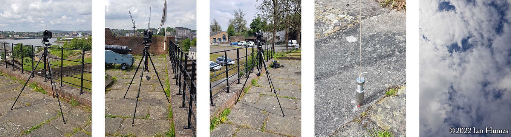
- Site visited and viewpoint is photographed under suitable lighting & weather conditions.
- Tripod location is marked (survey pin, paint, fixed geographic object etc).
- Produce Documentation Images
- Low-resolution proof images are provided to architects/clients and the required image is selected from those available.
- Provide site documentation to the surveyor including pin locations, selected images (A3 size), kmz file etc via secure download location.
- Provide a high resolution version of the selected image and the image data (time date, lens, rise, camera used etc.) associated with it to visualiser via secure website download.
- Produce Verified View Method Statement based upon the selected photographs.
- Locate the survey pin and set up the total station over it at the same height as the camera or near it so that the view seen isn't vastly different.
- Survey the view shown in the selected image using fixed points contained within the view.
- Mark-up A3 print of selected image with point cloud numbers generated by total station.
- Survey the survey pin if total station isn't positioned above it.
- Produce a point cloud for each viewpoint as a dwg (if requested).
- Produce a spreadsheet of point cloud coordinates and locations description (vp04, point 04012, (Easting, Northing & AOD), lower left corner of window frame).
- Supply point cloud information and spreadsheet to visualiser.
- Produce Methodology and Evidence document that includes spreadsheet with point cloud data included.
- Imports Point Cloud, Selected Image, 3D building Model and surrounding terrain/buildings into software.
- Create virtual camera to mimic camera used (type of lens, f-stop, amount of rise etc.) at surveyed viewpoint location.
- Align photograph to point cloud and terrain/building model.
- Position 3D building in geographically correct location.
- Set virtual world date and time to match when photograph taken (sun must be in the correct position for shadows to match photograph).
- Configure the light quality to match that on day (bright sunlight with high-contrast shadows, diffuse cloud with soft edged shadows, heavy overcast with minimal shadow) see Documentation Images
- Render building depending upon AVR level required (0-3 see below).
- Merge building and photograph into one image (make sure that objects in front of building obscure building (tree branches, chain-link fence etc.)) to create a photomontage of the proposed view.
- Produce Methodology and Evidence Document that includes final photomontages.
- Existing and proposed images/photomontages used in VIA document and Methodology and Evidence Document supplied as supporting evidence


Architects
Photographer
Surveyor
Visualiser
This is a very simplified version of the verified view workflow. Once it is complete the photographer, surveyor and visualisers can supply the client with the necessary data, photographs and photomontages enabling the client to define the photomontage as a verified view. If required the method statements and evidence can be supplied to third parties allowing them to recreate the final photomontage for verification.
The photographers Methodology and Evidence statement is usually the longest as they need to provide the most information to those working further down the chain. For example my current Verified View Method Statement is provided as a PDF in A3 format and contain 3 pages of local area images, 15 pages of supporting information and 3 pages of documentation for each viewpoint.
Looking at the above list you can see how the different disciplines need to work together and provide each other with information regarding their working practices. Wherever the verified view is located, whether it be a public park, long distance path or high street the photographer and surveyor will need to be able to set up a tripod and be undisturbed for up to an hour to complete their work. This needs to be taken into consideration when choosing viewpoints for verified views as it excludes "in roads", pedestrian crossings, railways (illegal to trespass on anyway) and many shopping centres/privately owned public spaces. Other locations that require permission "and a separate fee" to shoot from include but is not limited to, London Underground, Docklands Light Railway, Overground Stations and Royal Parks.
Here are some examples of completed Verified Views
Existing & Proposed Images


The "London View Management Framework" has the following to say regarding Verified Views/AVR's.
"By accurately combining an image of a proposed development with a representation of its existing context, all AVRs explain the location and massing of a proposed development. They may also illustrate additional properties including the degree of visibility, architectural form or choice of materials selected. In their most sophisticated form they give a very useful impression of how a completed development would look in its environment under specific lighting and weather conditions. When complex AVRs are requested, more time is required and therefore costs rise. For this reason the assessors of a project should be careful to only request AVRs of a type which show the properties which need to be assessed from a specific location. To assist agreement between all parties prior to AVR preparation, the following classification types are presented to broadly define the purpose of an AVR in terms of the visual properties it represents. This classification is a cumulative scale in which each level incorporates all the properties of the previous.
AVR Level 0 : Location and size of proposal.
AVR Level 1 : Location, size and degree of visibility of proposal.
AVR Level 2 : as level 1 + description of architectural form.
AVR Level 3 : as level 2 + use of materials."
Please find below examples of the different levels of AVR.
AVR Levels


Interested in learning more?
If you've looked through my site and have any questions, I'd be glad to help you. You can contact me on my mobile on 07801 103635 or send me an E-mail and I will get back to you as soon as I can.